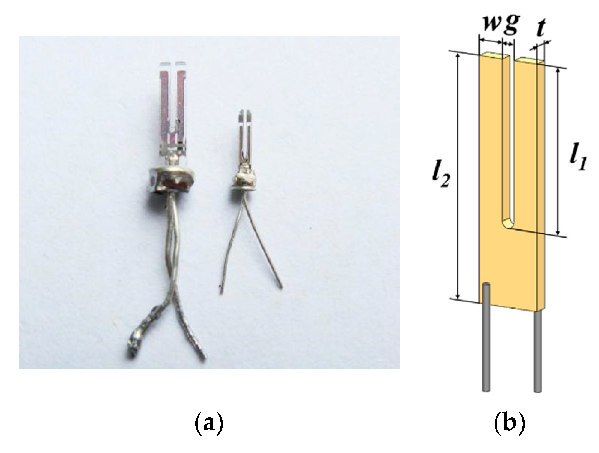

Parts (a), (b), (f), and (g) illustrate the geometrical dimensions as listed in Table 1 parts (c) and (h) show a schematic view of the electrostatic field in the cross sections and parts (d) and (i) show the mechanical stress profile along a cross section. A needle sensor (f) is built by attaching a light tip to one prong of the length-extensional resonator. The prong without displayed electrodes is fixed to a massive substrate (not shown here see Fig. 2b).
Quartz tuning fork sensor free#
For clarity, only the electrodes on the free prong are shown. A qPlus sensor (a) is created by attaching one of the prongs of the tuning fork to a substrate and attaching a tip to the other prong. Finally, we suggest how the signal-to-noise ratio of the sensors can be improved further, we briefly discuss the challenges of mounting tips, and we compare the noise performance of self-sensing quartz sensors and optically detected Si cantilevers.įigure 3Geometry of sensors based on quartz tuning forks (a)–(e) and length-extensional resonators (f)–(j).

Thus, we show that the earlier finding that quoted an optimal signal-to-noise ratio for oscillation amplitudes similar to the range of the forces is still correct when considering all four frequency noise contributions. The first three noise sources are inversely proportional to amplitude while thermal drift noise is independent of the amplitude. Thermal drift noise, however, is inversely proportional to bandwidth. Deflection detector noise increases with bandwidth to the power of 1.5, while thermal noise and oscillator noise are proportional to the square root of the bandwidth. We find that for self-sensing quartz sensors, the deflection detector noise is independent of sensor stiffness, while the remaining three noise sources increase strongly with sensor stiffness. We calculate the effect of these noise sources as a factor of sensor stiffness, bandwidth, and oscillation amplitude. We find four noise sources: deflection detector noise, thermal noise, oscillator noise, and thermal drift noise. Here, we calculate and measure the noise characteristics of these sensors. Two fundamentally different types of quartz sensors have achieved atomic resolution: the “needle sensor,” which is based on a length-extensional resonator, and the “qPlus sensor,” which is based on a tuning fork.
Quartz tuning fork sensor upgrade#
These self-sensing force sensors allow a relatively easy upgrade of a scanning tunneling microscope to a combined scanning tunneling/atomic force microscope. Nowadays, most atomic force microscopes use micromachined force sensors made from silicon, but piezoelectric quartz sensors are being applied at an increasing rate, mainly in vacuum. ) for qPlus sensors and energy balance principle generally for quartz resonators, rather than the theoretical approach.The force sensor is key to the performance of atomic force microscopy (AFM). For accurate calibration of oscillation amplitude, one can use experimental methods based on thermal noise spectrum (method (b) in Ref. The electrical signal in volts (left vertical axis) was converted into mechanical amplitude in nanometers (right vertical axis) by using a theoretical method (method (a) described in Ref.

We used two tuning forks with different sizes, electrically driven tuning fork (ED-TF) A and ED-TF B ( a, c), and they were transformed to qPlus sensors, ED-qPlus A and ED-qPlus B ( b, d), respectively. From each fit, we could uniquely determine the dynamic characteristics shown in Equation (1), A 0, Q, f 0 ( = w 0 / 2 π ), and C ¯ 0 ( = C 0 / C ), for each probe. These curves were well fit by Equation (1) derived from the equivalent circuit model (Figure 1c). The electrical signals of the tuning fork ( a, c) and qPlus ( b, d) showed asymmetric curves with one peak and one local minimum. Electrically measured resonance curves of the bare tuning fork and its qPlus configuration (both electrically driven).


 0 kommentar(er)
